¶ Overview
- The Ascent HD system supports a passthrough function. It uses the 5.8 GHz wireless video transmission link to carry radio control signals, providing a cost-effective solution for long-range Drone control.
¶ When to Use this Guide
- This function uses the video transmission link as a transparent data channel to forward CRSF receiver signals. It supports bidirectional data passthrough and can relay CRSF radio control signals for long-range control.
- The control link is completely dependent on the video transmission link. If the video link is interrupted or affected by interference, the radio control passthrough link will also be affected. Before use, make sure safety features such as failsafe Return-to-Home are properly configured to prevent loss of control.
¶ CRSF Receiver Passthrough
¶ Setup Procedure
¶ Step 1: Confirm the Firmware Version
- Update both the Ascent VTX and Ascent VRX to firmware version 18.21.13 or later.
¶ Step 2: Configure the VRX Menu
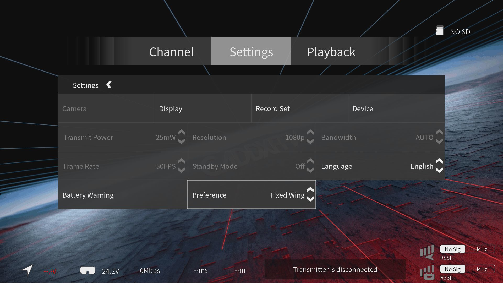
- On the Ascent VRX, go to Menu > Settings > Preference and select Fixed-Wing.
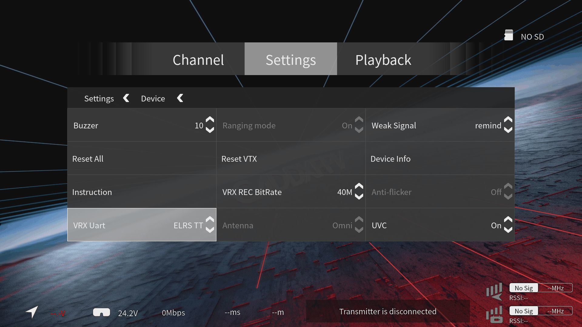
- Then go to Menu > Settings > Device > VRX UART and set it to ELRS Passthrough.
¶ Step 3: Connect the Air Unit to the Flight Controller
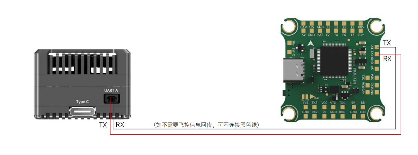
- Connect UART A on the Ascent VTX to an available UART on the flight controller as shown below. UART1 is used as an example.
¶ Step 4: Connect the Radio Receiver to the Receiver Unit
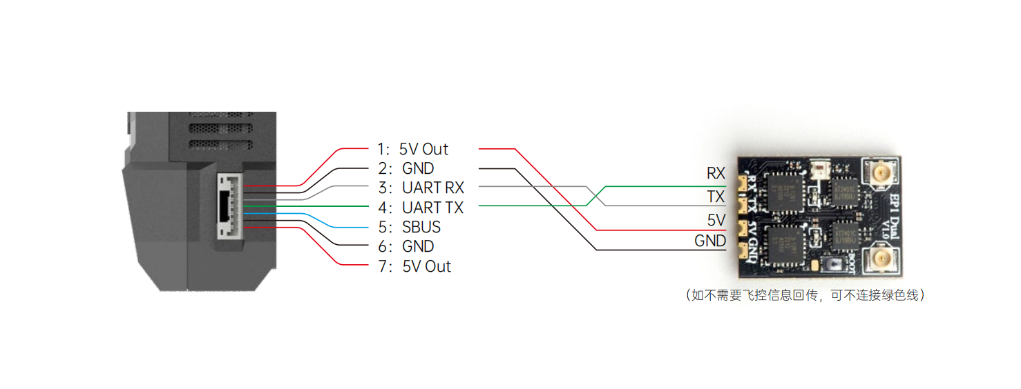
- Connect the CRSF receiver to the VRX passthrough UART port.
¶ Step 5: Configure the Radio Controller
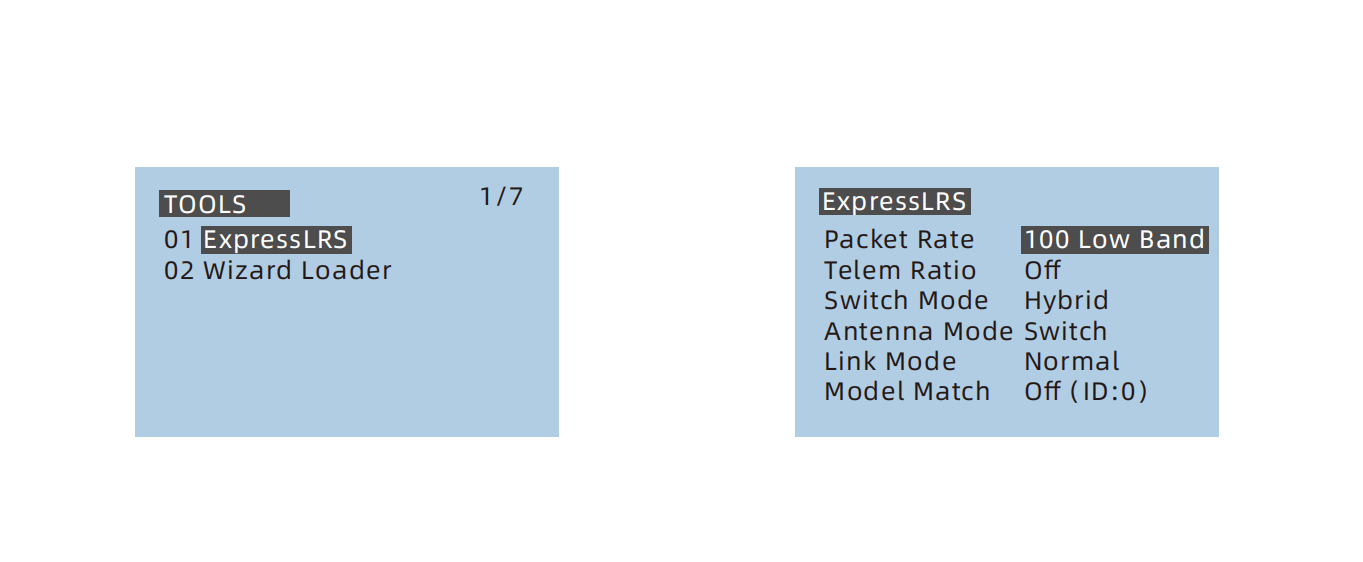
- After Binding the radio controller and receiver, set the radio controller Packet Rate to 100 Hz or lower.
¶ Step 6: Configure the Flight Controller
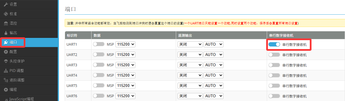
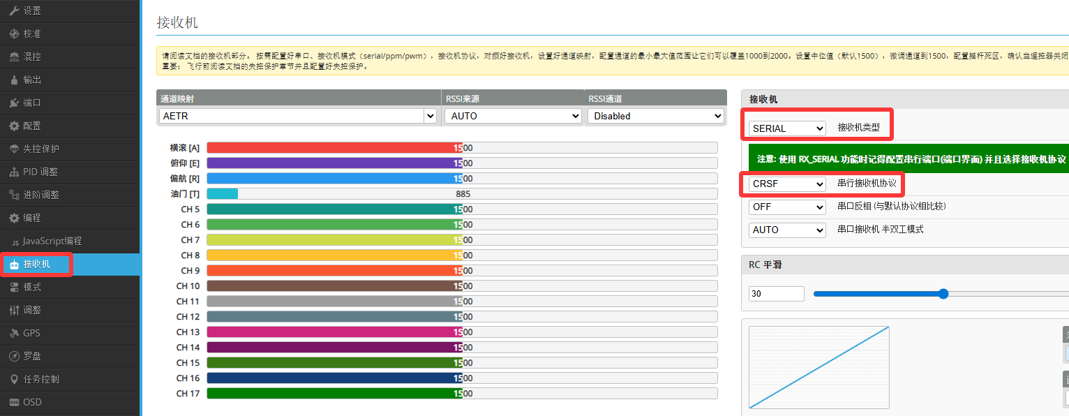
- In the flight controller configurator, enable the receiver function on the corresponding UART. The example below uses INAV Configurator. Configure the settings according to the highlighted options, then verify that the flight controller is receiving channel data correctly.
¶ S.BUS Receiver Passthrough
¶ Setup Procedure
¶ Step 1: Confirm the Firmware Version
- Update both the Ascent VTX and Ascent VRX to firmware version 18.21.13 or later.
¶ Step 2: Connect the VRX
- Connect the S.BUS port and GND on the Ascent VRX to the S.BUS output and ground of the radio controller or receiver.
¶ Step 3: Configure the Radio Controller
- Set Internal RF on the radio controller to Off, and set External RF to SBUS.
¶ Step 4: Connect the Air Unit to the Flight Controller
- Connect SBUS and GND on the Ascent VTX to the corresponding S.BUS receiver input and GND on the flight controller. For example, this may be RX2 and GND. Refer to the flight controller documentation and use the designated S.BUS input.
¶ Step 5: Configure the Flight Controller
- In the flight controller configurator, enable the receiver function on the corresponding UART. The example uses Betaflight Configurator. Configure the settings according to the highlighted options, then verify that the flight controller is receiving channel data correctly.
¶ Step 6: Reflash the Flight Controller Firmware
- If the flight controller cannot receive the S.BUS signal, try reflashing the flight controller firmware and select S.BUS as the receiver protocol. After flashing is complete, repeat Step 5 to configure the receiver.
¶ Notes
Low Latency Mode does not support CRSF or S.BUS passthrough. Only UART control is supported in this mode.
Set the radio controller Packet Rate to 100 Hz or lower. Higher packet rates may result in packet loss and loss of control.
This function is completely dependent on the video transmission link. If the video link is interrupted or affected by interference, the radio control passthrough link will also be affected. Before use, make sure safety features such as failsafe Return-to-Home are properly configured to prevent loss of control.
When using the passthrough function, the receiver is not physically installed on the Drone. Therefore, the radio controller cannot obtain accurate RSSI or LQ data, and the receiver signal information displayed in the flight controller OSD will not be accurate. The radio controller will also be unable to trigger a signal-loss warning when control is lost.