¶ When to Use this Guide
- For first-time FPV drone users who do not know how to connect the wiring.
¶ What You Need
- One T12 soldering iron
- One roll of high-quality solder wire
- One Walksnail HD digital VTX
- One flight controller
¶ Procedure
¶ Step 1: Choose a Flight Controller
- Flight controller designs generally fall into two types.
- The first type is the full solder pad design, where every component connection must be soldered. Full solder pad flight controllers are less common nowadays, and most models include at least some connectors.
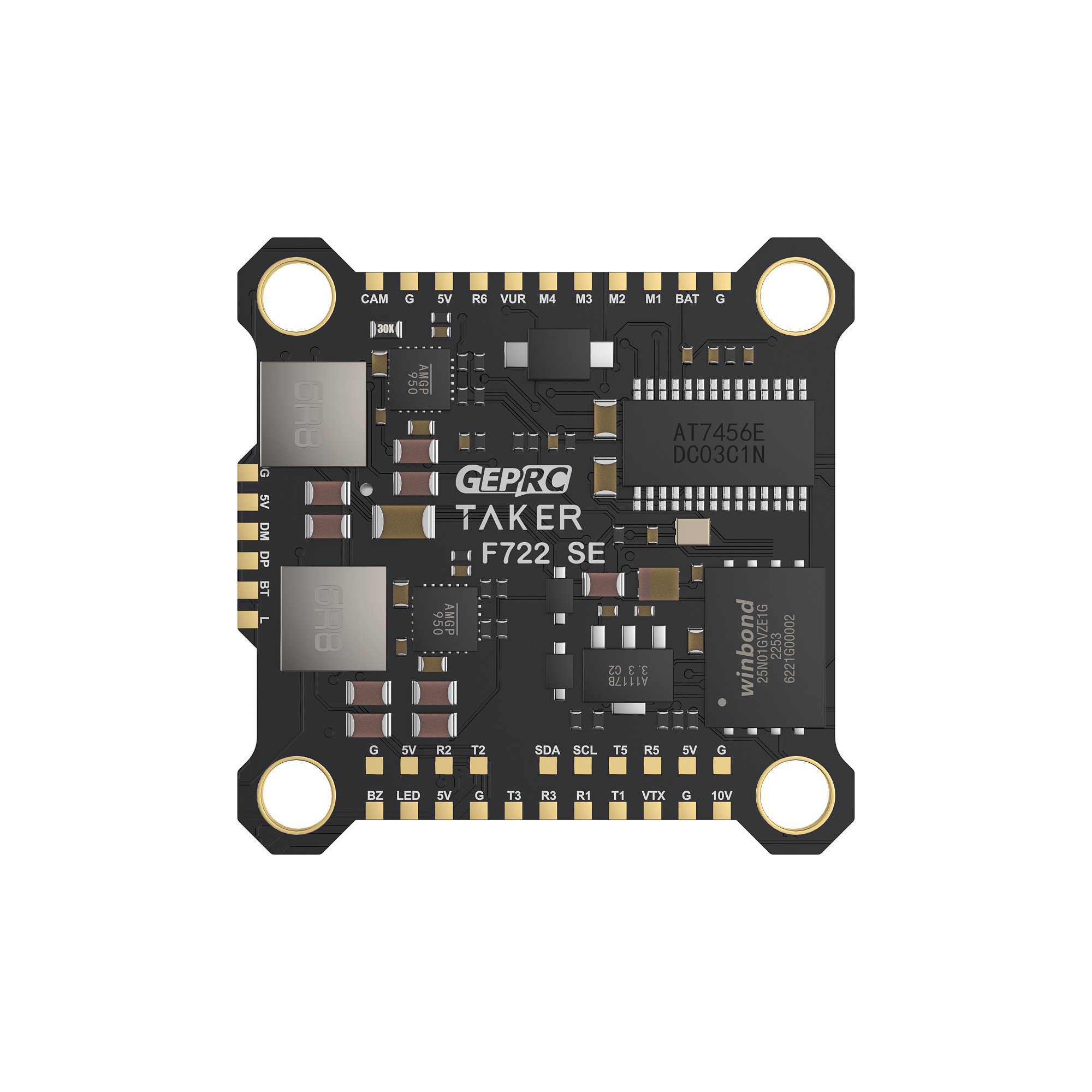
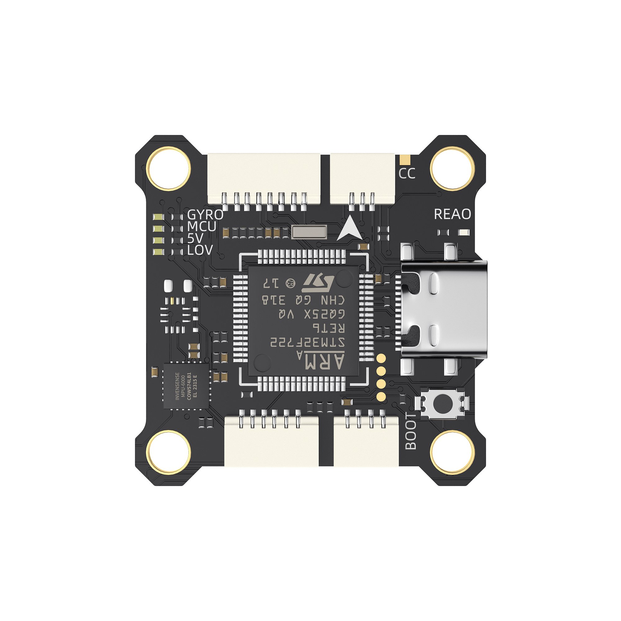
- The second type uses plug connectors, making component replacement much easier because you only need to plug and unplug the cables.
¶ Step 2: Confirm the Power Supply
- Each flight controller manufacturer has a different design approach, so the power circuitry may vary from model to model.
- First, check the specifications of the flight controller itself to confirm whether it includes a built-in 9V / 12V BEC step-down circuit. Some flight controllers only provide a 5V BEC.
- Second, you must carefully check the input voltage range of the Walksnail digital VTX you purchased. Most VTX units support a wide voltage range, but some models have specific voltage requirements.
- For example, the
Avatar 1SVTX only supports 5–13V, while theAvatar GTonly supports 12–26V. If the flight controller does not support 12V output, then the power must be connected to VBAT, which is the direct battery voltage.
Using the wrong voltage may cause unstable operation or even permanently damage the device, so be sure to check carefully!!!
See the product comparison tables below:
Avatar Product Comparison Table
Ascent Product Comparison Table
¶ Step 3: Connect the Wiring
¶ Cable Plug Connection
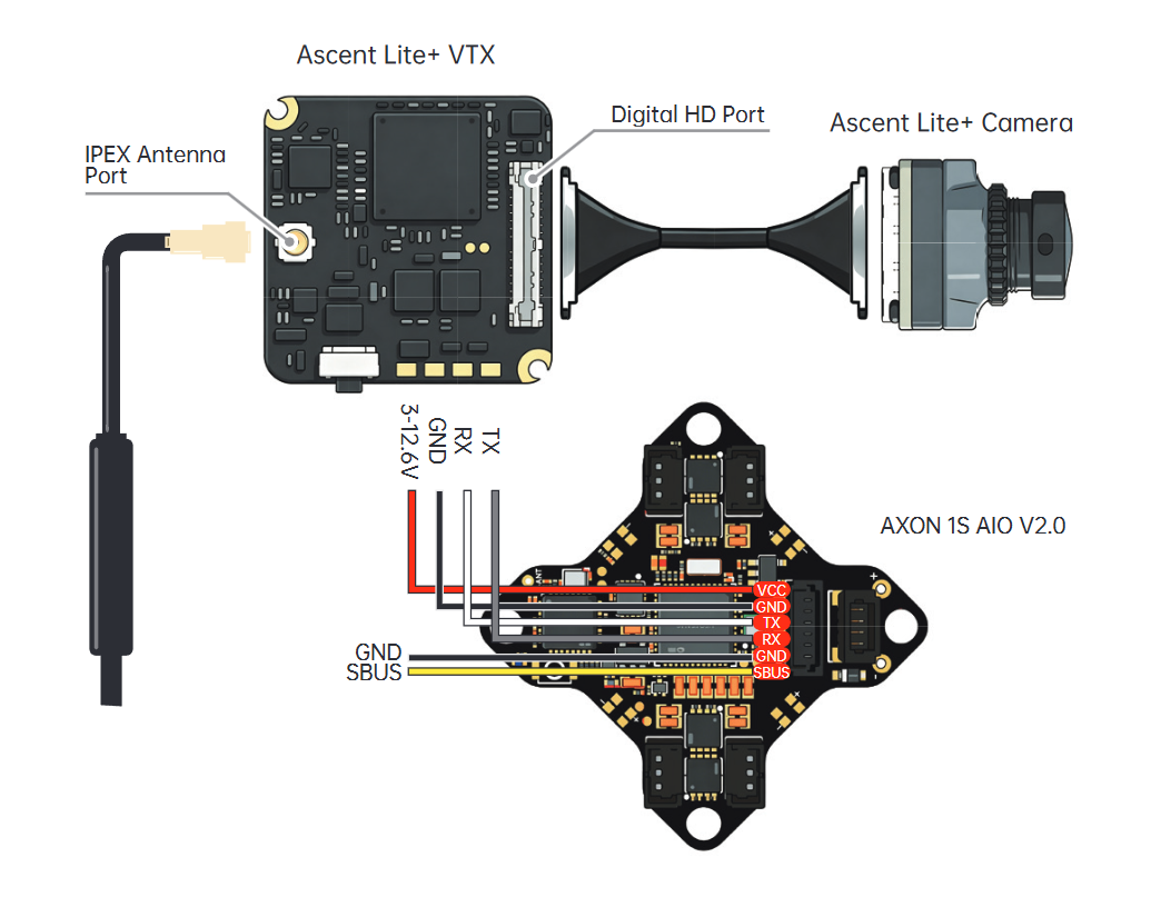
- Using the
Ascent Lite+VTX as an example, it comes with a pre-soldered cable from the factory, so using the plug-in method is recommended. - Simply plug the
Ascent Lite+into the connector on the flight controller, avoiding the need for soldering. - On most flight controllers, the connector pinout is usually the same:
VCC, GND, TX, RX. In most cases, the cable can be used directly without changing the wire order. However, you should still double-check the pinout carefully before use to ensure it is correct.

¶ Solder Pad Connection
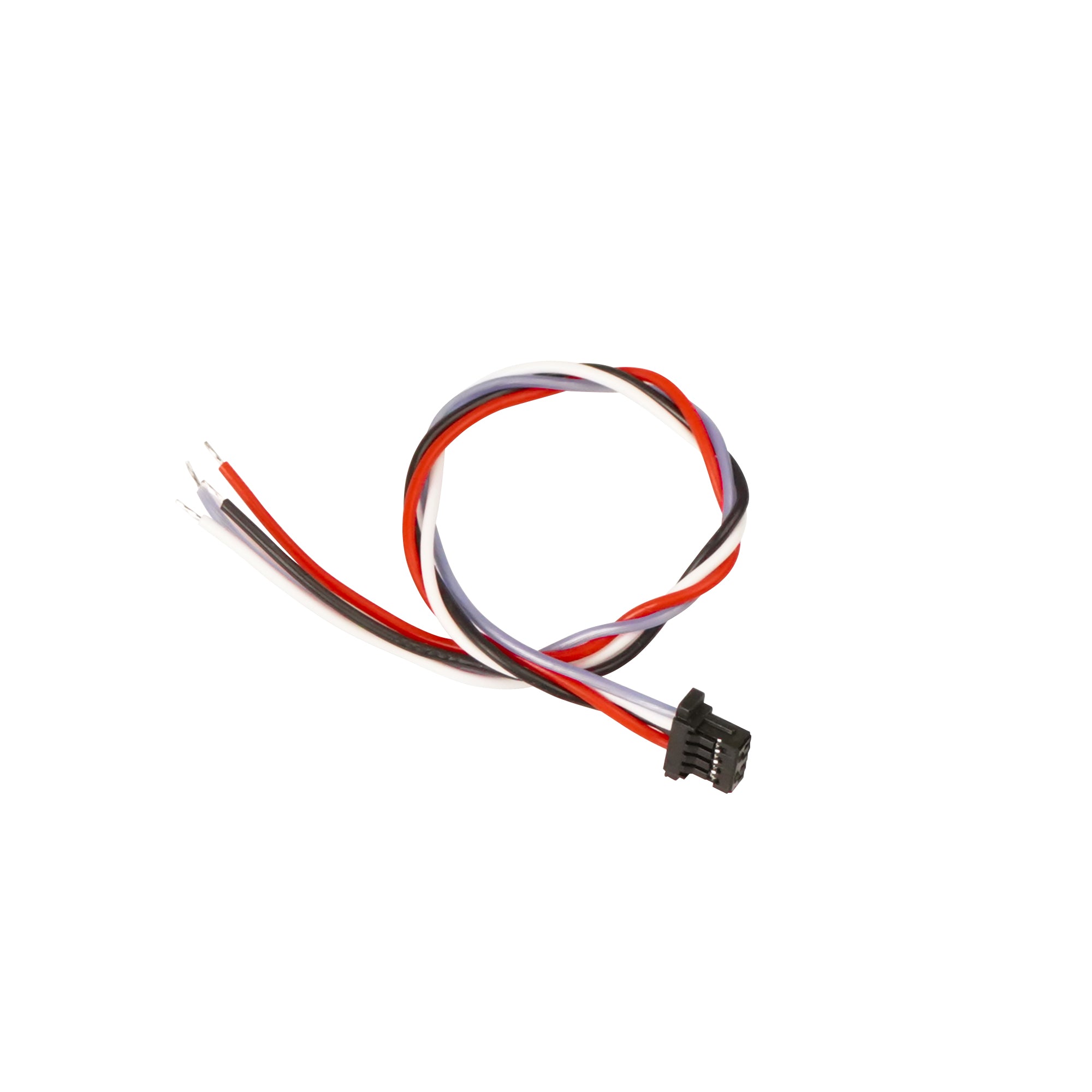
- If the flight controller only supports solder pad connections, the plug must be cut off, and the internal copper wire should be stripped to about 2 mm. If it is stripped too long, it may easily cause a short circuit.
-
Set the soldering iron temperature to 350°C, tin the pads and wires, and solder them according to the wiring diagram.
-
Beginners are advised to practice first on a scrap PCB board before working on the actual device, so they can become familiar with soldering techniques.
-
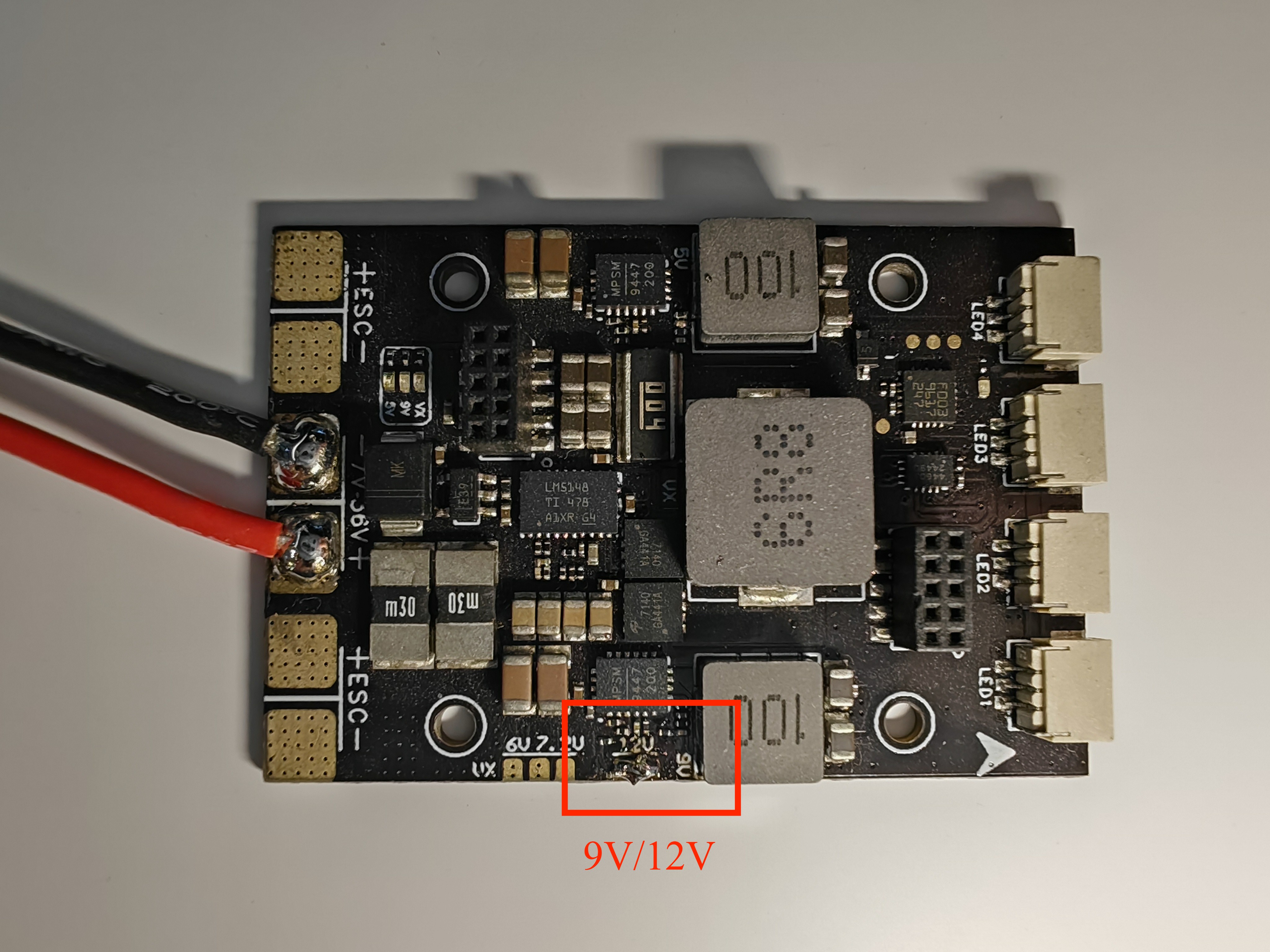
Using this flight controller as an example, it supports a voltage selection jumper pad. By default, it is set to 9V. After soldering the jumper pad, it switches to 12V, which meets the 12V requirement of the
Avatar GT.
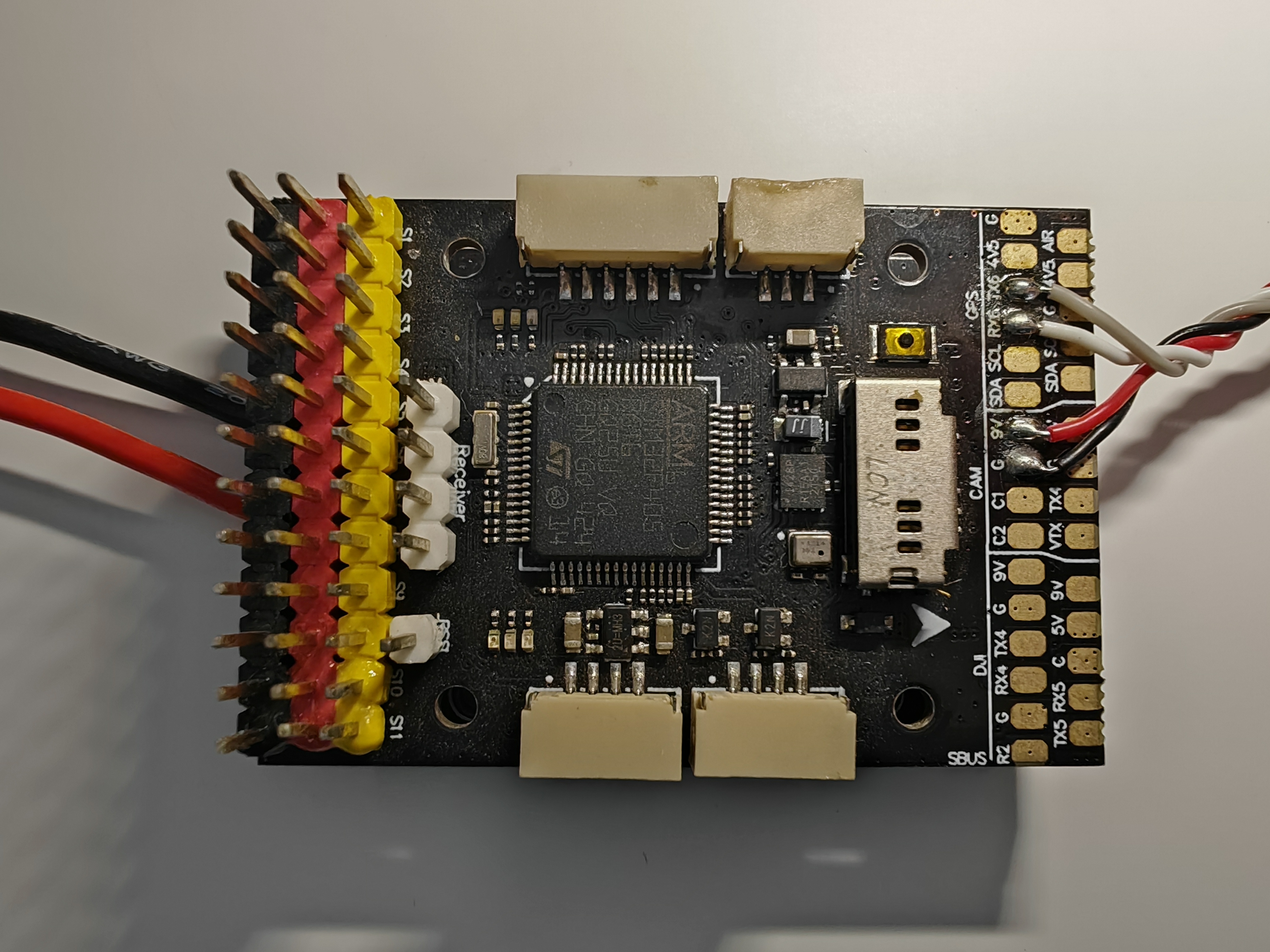
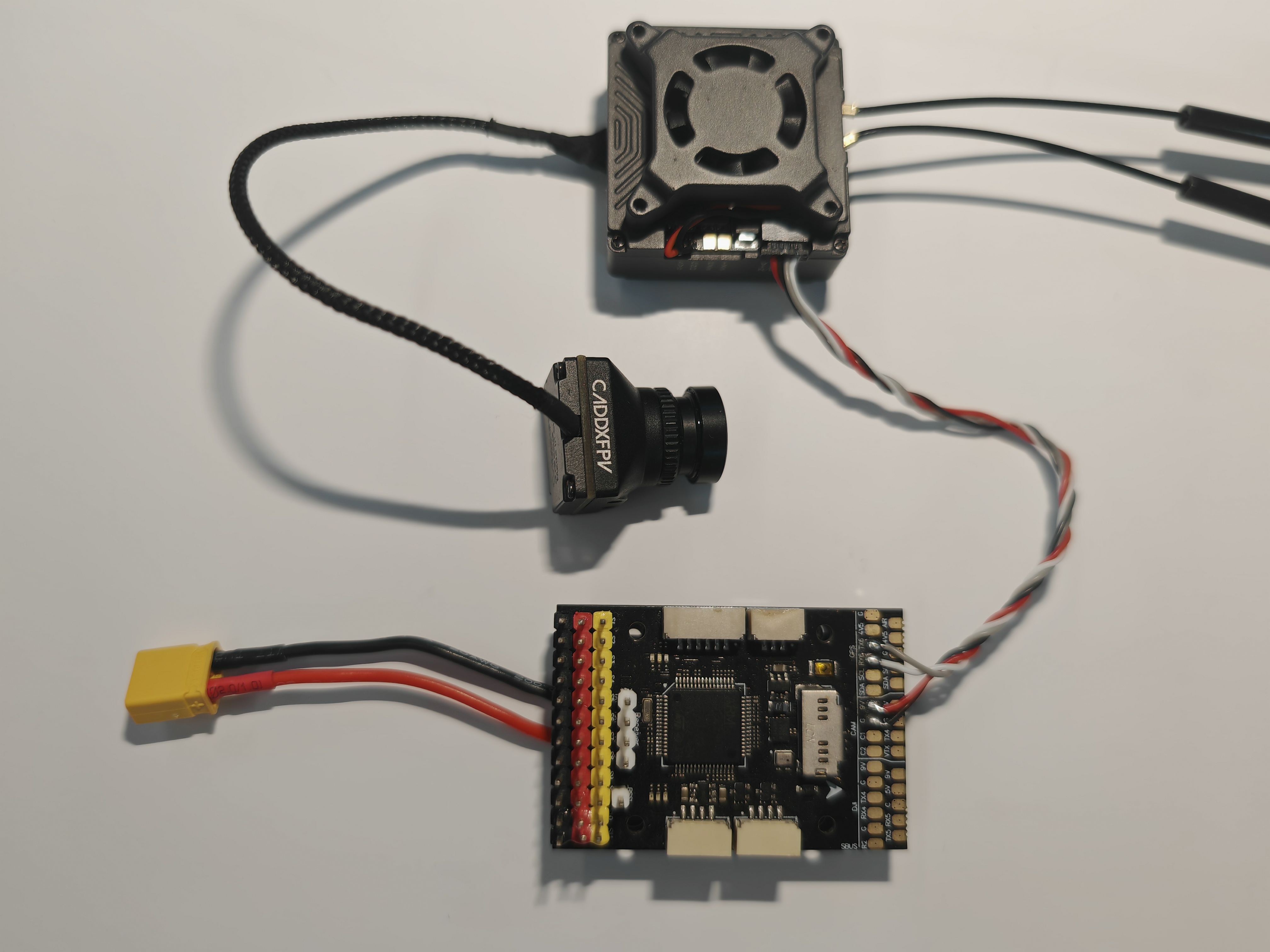
- Then solder the power cable included with the VTX kit onto the flight controller. Connect
VCC, GND, TX, RXfrom the VTX cable to the corresponding pads9V / VBAT, GND, RX, TXon the flight controller. - Note that for the UART connection, TX and RX must be cross-connected. Do not connect RX to RX or TX to TX, otherwise data cannot be transmitted.
¶ Important Notes
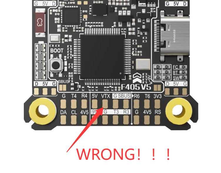
Some beginners may mistakenly connect the RX/TX wires from an HD air unit to the VTX pad on the flight controller. This is incorrect. The VTX pad on the flight controller is used for the video signal wire of an analog VTX. It can only be connected to an analog VTX and must not be connected to an HD air unit!!!
For the UART connection, TX and RX must be cross-connected. Do not connect RX to RX or TX to TX, otherwise data cannot be transmitted.